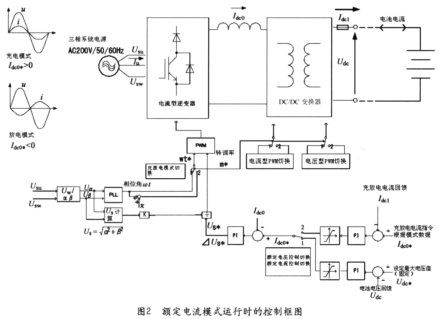
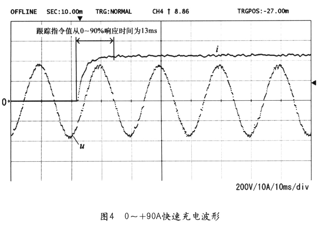
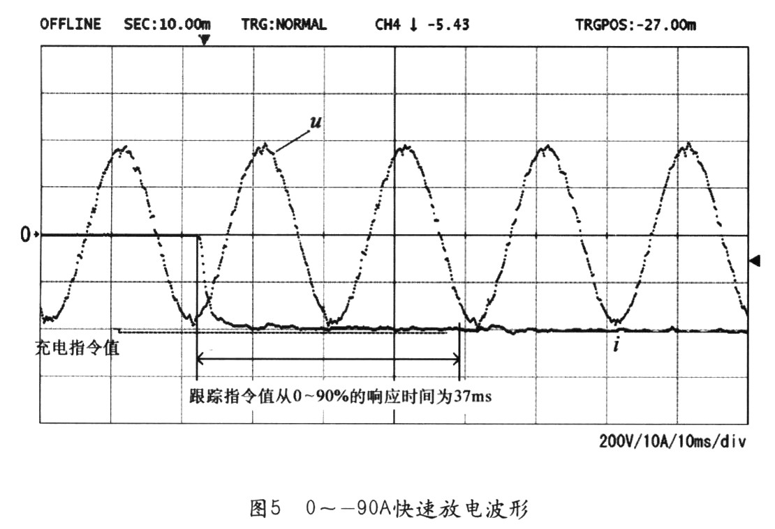
(3) Control block diagram Figure 2 is the control block diagram of APL2 constant current mode operation. When the charge/discharge operation is performed, the mode data downloaded from the computer is used as the current command value to perform constant current control. During the charging process, when the battery voltage reaches the preset maximum voltage value, it automatically switches to the constant voltage control mode and the trickle charging mode. It can be seen from Fig. 2 that the charge and discharge command in the loop is switched by the contact circuit, but actually, the program is switched by using the DSP, and the switching time delay hardly occurs. When the APL2 is used as a battery charge and discharge device, it is possible to directly apply its circuit characteristics for control without changing any internal configuration. In this system, the rated voltage and current of APL2 is 400V/25A. In order to expand the capacity, the master-slave function is used. The maximum APL2 can be connected in parallel to achieve a charge and discharge current of 100A. Figure 4 shows the charging voltage and current waveform of 0 to +90A elbow. When the battery is charging, the current waveform changes stepwise. Figure 5 shows the charging voltage and current waveform when the battery is 0 to -90A. The response waveform when the current changes stepwise. Regarding the battery current, the output current of the host APL2 is specified first, and the slave changes with the charge/discharge current command value of the host. The system can perform fast S-speed charge and discharge control at a current of about 100 A, and can be used for the basic charge and discharge characteristics test of a lithium ion battery. Golf Club Set,Golf Club Protection,Golf Knitted Club Cover,Crocodile Pattern Golf Caps Grand Dragon Sports Company Limited , https://www.golfyy.com
1 System Configuration (1) Overview There are two main circuit configurations for battery charge and discharge devices. One is composed of a linear amplifier (charger) + an impedance load (discharger), etc., hereinafter referred to as composition 1; and the other is composed of a system inverter + a bidirectional converter (charger and discharger), hereinafter referred to as composition 2, Let's compare the superiority of the two.
At present, about half of the battery chargers currently on the market are constituted by 1, and the charger device of this configuration has a fever phenomenon and a large volume, and has a certain limit on the place where it is placed. When operating as a discharger, the configuration 2 is optimal if it is desired to transmit energy bidirectionally.
Here, for the configuration 2, the following two different circuit design methods are discussed.
The first design method is to combine a voltage type system combined inverter and a bidirectional step-up step-down frequency converter as a battery charging and discharging device, and the second design mode uses a large-capacity power supply and an electronic load device (hereinafter referred to as APL2). The APL2 can be used to change the battery voltage and current arbitrarily. As a power supply or load, it can input and output 10 kW (operating voltage is 0 to 200V or 400V).
In the first design method, there are certain problems in the miniaturization of the insulation transformer between the system and the power grid, the reactor of the buck-boost inverter, and the switching unit. At the same time, in the high-frequency transformer attached insulation circuit, in order to suppress the pulsating current of the battery, the buck-boost converter and the reactor are indispensable.
In the second design, the APL2 is used, and it is not necessary to change the circuit according to the change in the rated capacity of the battery. At the same time, it has the characteristics of increasing the charge and discharge current through the series circuit and being small and lightweight.
As a case of the design scheme, under the design conditions of the same rated capacity of 10 kVA, the result of the design comparison is that the device volume of the second design mode is 1/2 of the first design mode. Based on the above analysis and comparison, this paper uses the APL2 battery charging and discharging device.
(2) Basic structure The system is simple to set up and can be connected to the APL2 and the user's computer through only one optical cable. At the same time, using this system, the development of battery charging and discharging system under windows system can be realized, as shown in Figure 1. 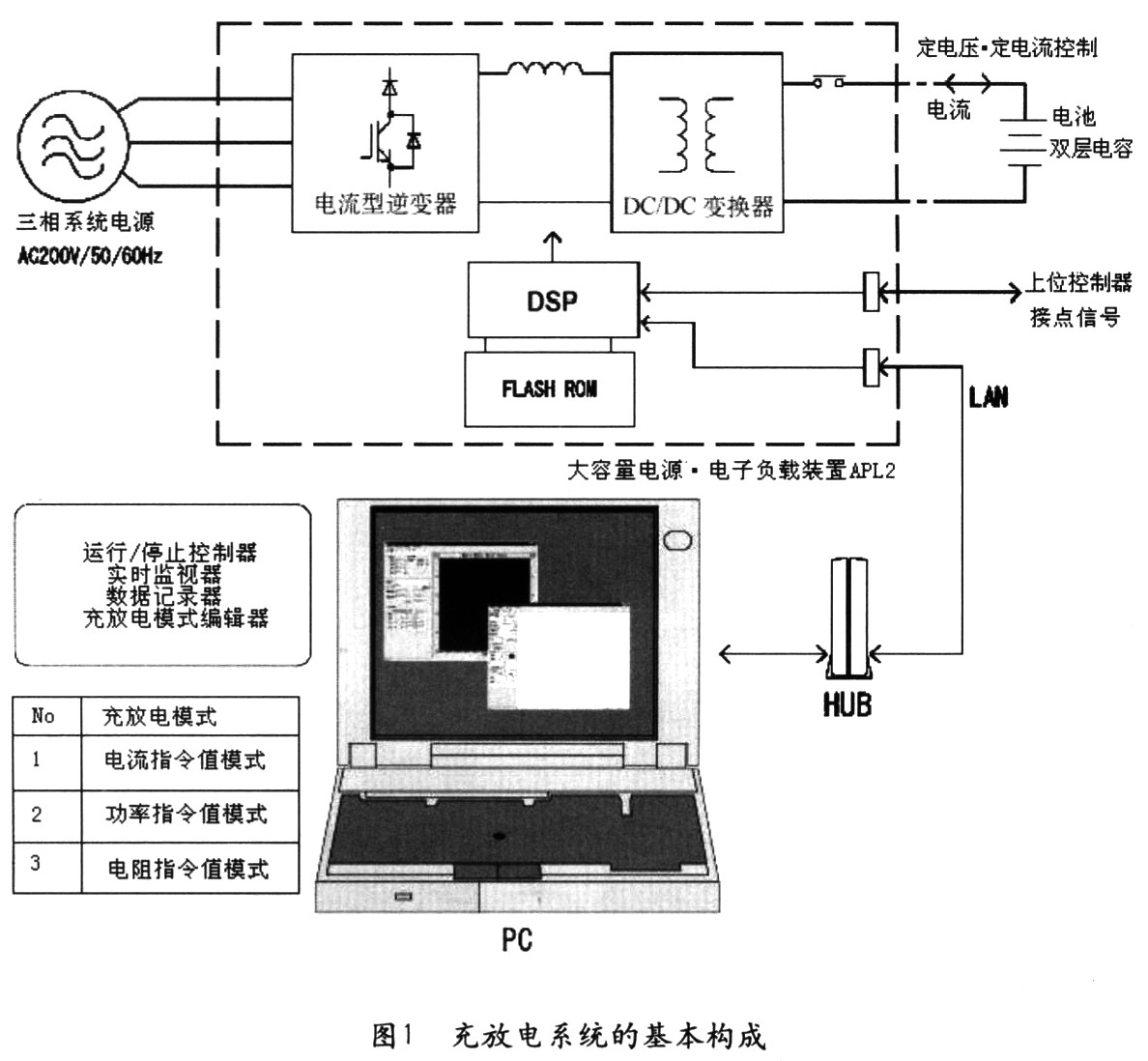
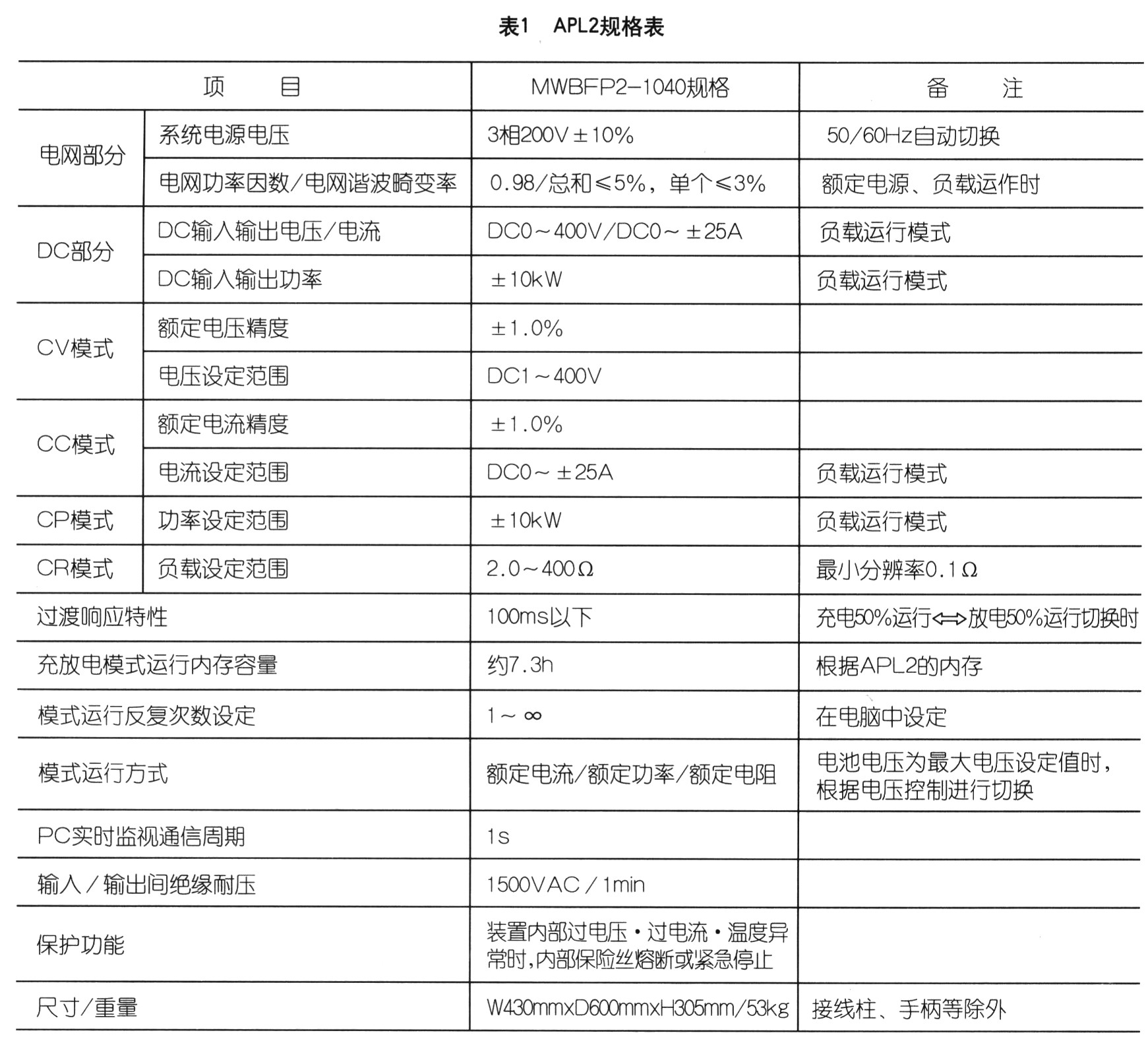
2 Application example The following describes a charge and discharge system for a high-capacity, high-voltage ion battery using APL2. As a charge and discharge target, the battery unit has a maximum voltage of 336V and a charge and discharge current of ±100A. Figure 3 shows the structure of the system, and Table 1 shows the basic specifications of APL2. 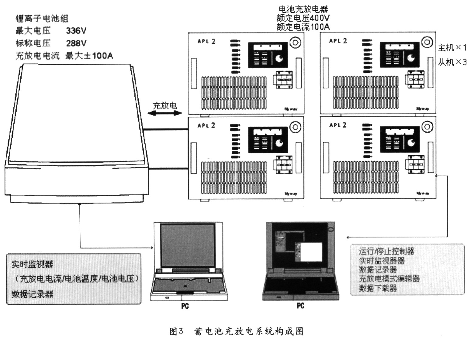
3 Conclusion According to this design method, the APL2 device can be directly used in a large-capacity battery charging and discharging system to realize a small and lightweight system, and the system development time is shortened accordingly. In this paper, the application of APL2 to the charging and discharging system of lithium ion battery is introduced. It can also be used in the charging and discharging system of double-layer capacitors , and the power supply system of HEV·EV motor 9 zone system, etc., and has space saving. And save energy features.
Battery charging and discharging system design
Introduction In recent years, with the popularization of automobiles, the displacement of NOx and COx has been increasing, and environmental pollution and global warming have become increasingly serious. To this end, many countries are actively promoting hybrid electric vehicles and electric vehicles to replace traditional cars. But more importantly, these new energy vehicles need energy storage media with high energy density, high voltage, fast charge and discharge characteristics, such as lithium-ion batteries. As a practical charge and discharge device, the battery has the greatest effect, and its requirements for large capacity, high precision, and reliability have also been improved. In order to effectively play the battery performance, this paper will provide a design method for a large capacity battery charge and discharge system.