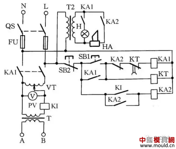
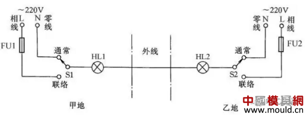
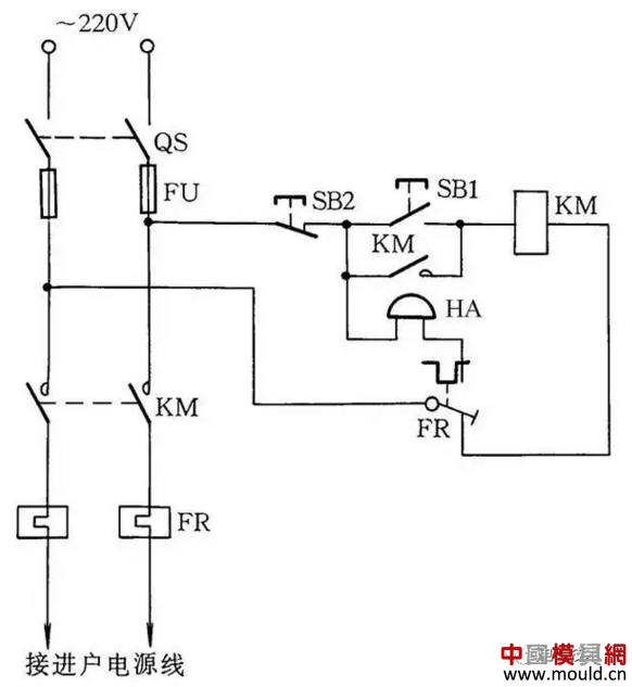
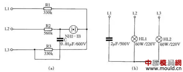
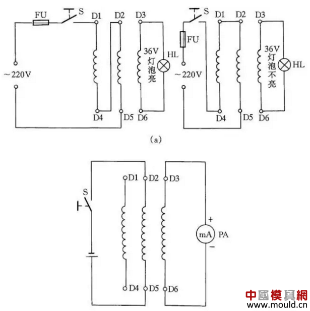
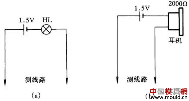
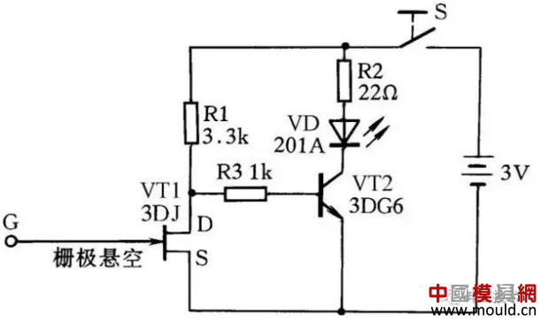
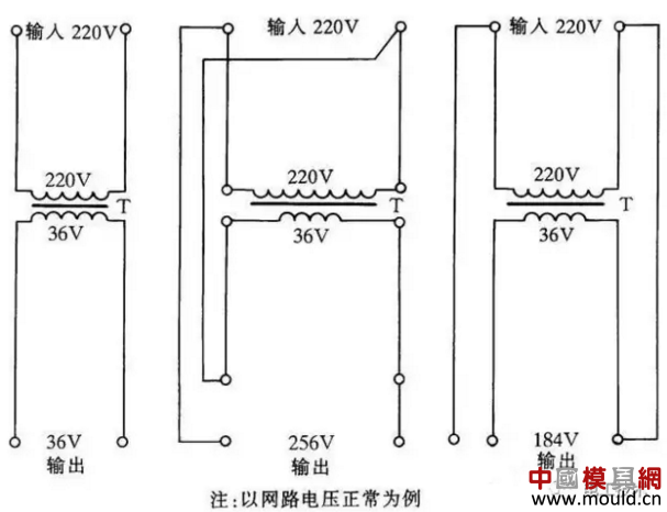
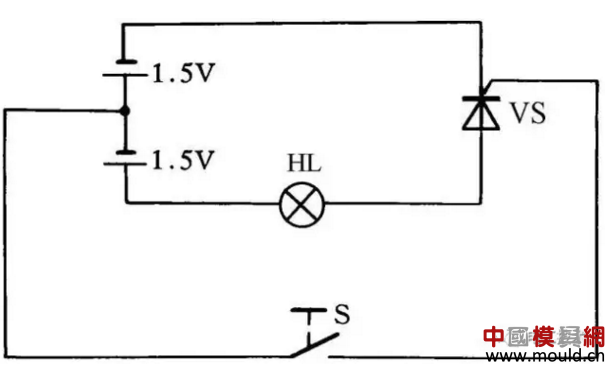
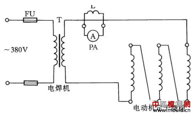
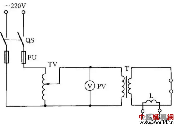
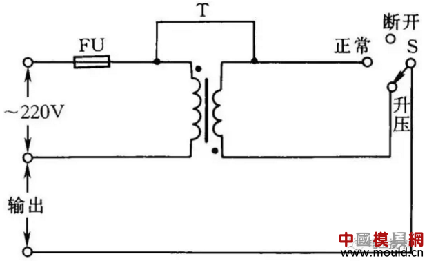
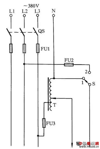
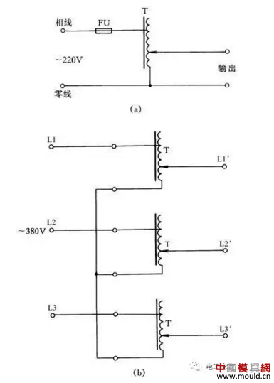
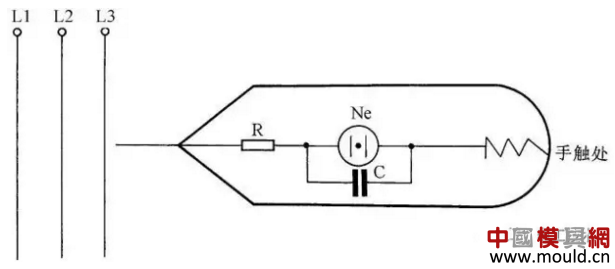
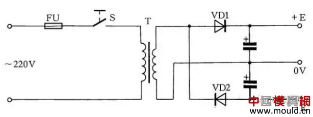
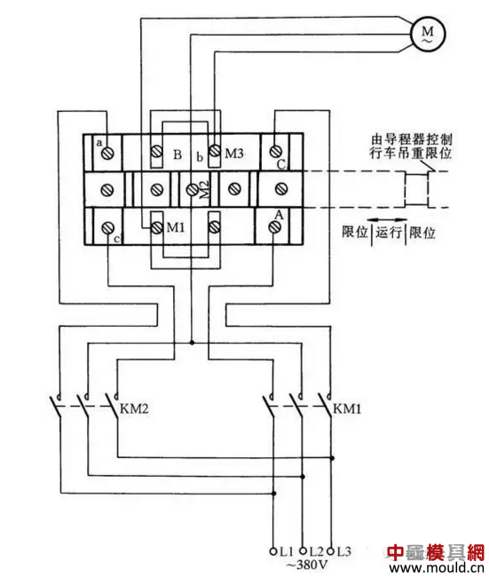
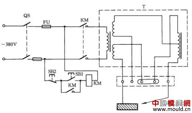
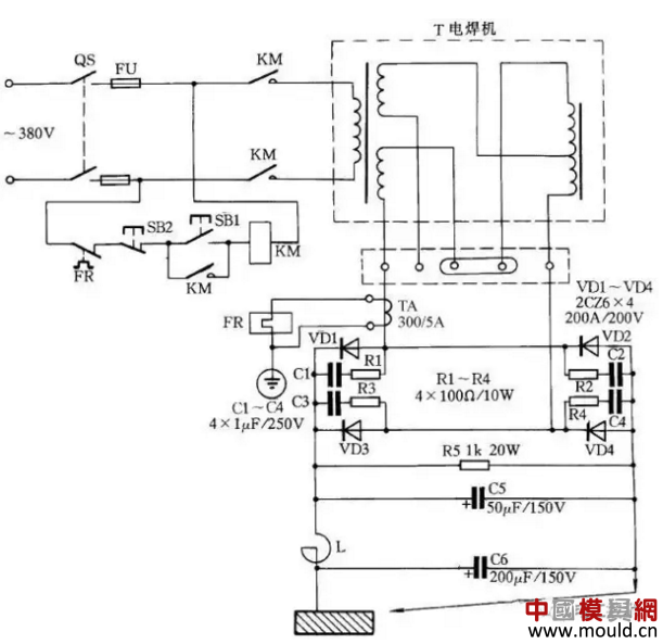
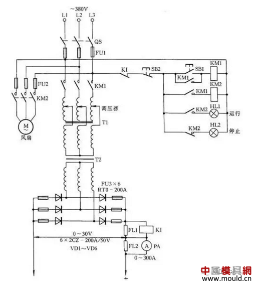
Received 10 years of experience in electricians and cattle yesterday, summarized 41 methods of wiring (Part I) 21 , insulation withstand voltage tester line This kind of insulation voltage tester can measure lamps, connect the lamp to be tested with A, B two terminals, press the button SB1, the intermediate relay KA1 get electricity and self-locking; then the pressure regulator VT (1:10, Output 0~250V) Adjust to the voltage value to be measured. If it needs to adjust to 1500V, then adjust VT to the voltage meter to indicate 150V. (For the same reason, when it is 2000V, adjust the indicator to 200V in the voltmeter.) After the power is turned off, see Figure 21. If the insulation breakdown of the measured object, the current rapidly increases, over-current relay KI action, KA2 get electric action and self-locking, KA1 loses power, KA1's normally open contact cuts off the main circuit power supply, buzzer HA sounds, press After the lower SB2 circuit is all off. When applying this type of instrument, special attention must be given to personal safety. When the power is applied, the high-voltage test area is prohibited from approaching. Figure 21? Insulation tester line 22 , use a wire to transmit the contact signal line Figure 22? Use one wire to transmit the contact signal line In some production processes, it is necessary for production personnel in both places to transmit simple information to coordinate work. Figure 22 shows the transmission of a contact signal line with a wire. Each of the two places has a double-throw switch control signal lamp. The signal lights are installed in two places, one at a time. When A sends a contact signal to B, the switch S1 is toggled, and the indicator light of B is turned on. After B has completed the task indicated by A, B can dial the switch to the “contact†position to inform A. completed. 23 , using a single line to send signals to the control room The circuit shown in Figure 23 allows both A and B to send contact signals to the general control room. When A to send a signal to the general control room, press the button SB1, the alarm bell in the control room. Similarly, press SB2 when B sends a signal to the general control room. The length of time or number of signal tones can be used to distinguish between A and B signals. Figure 23? Signal the control room with a single wire 24 , the use of thermal relays to create limiter circuit Thermal relays are mostly used for motor overcurrent protection, but they can also be used as limiters in some collective power units or places where electricity is used. The specific production method is shown in Figure 24. When the thermal relay is manually reset, the thermal relay reset screw must be unscrewed. The rated current of the selected thermal relay is the same as the total rated current of the user. Figure 24? Using Thermal Relays to Create Limiting Circuits 25 , two self-installed AC power phase sequence indicator A small power phase sequence indicator can be formed with resistors, capacitors, and helium bubbles. When the power is connected in phase sequence L1, L2, L3, the Xenon lamp is on; when connected in reverse phase sequence L2, L1, L3, the Xenon lamp is off. The circuit is shown in Figure 25(a). The second method is to use a 2μF capacitor with a 500V withstand voltage and two incandescent bulbs of the same power (220V/60W) to create an AC power phase sequence indicator, as shown in Figure 25(b). Figure 25? Two self-contained AC power phase sequence indicators Working principle: Because of the phase shift of the capacitor, the phase difference of one phase is changed, and the vector voltages acting on HL1 and HL2 are not equal, and the rule is that the L2 phase vector voltage is greater than the L3 phase vector voltage. Therefore, after connecting as shown in Figure 25(b), the capacitor is connected to the L1 phase of the power supply. It can be seen that the stronger end of the bulb is the L2 phase and the weaker end is the L3 phase. 26 , two ways to determine the end of the three-phase motor windings When the motor's six lead wires cannot be identified, we can use AC power and light bulbs to check the head and tail of the three-phase winding of the motor to avoid misalignment of the windings. Figure 26? Two Methods for Measuring the Head and Tail of Motor Three Phase Windings The method for determining the three-phase winding of the motor by using the AC power supply and the bulb is as follows: First, use a 36V low-voltage lamp as a test lamp, and separate the two wire ends of each phase coil of the motor, and then connect the two-phase coils in series to the 220V power supply. After the next phase of the lamp coil connected to the two ends of the 36V line, the light bulb is illuminated, indicating that the two phases in series are connected head to tail; the light bulb does not light, indicating that the head is connected, as shown in Figure 26(a). Show. Then measure the two-phase coil head and tail as a mark, and then according to this method, one of the phases is connected in series with the original one-phase coil of the light bulb, and the other phase is connected to the light bulb. Then the same reasoning is used to judge the head of the three-phase winding of the motor. The tail is very easy to distinguish. Another method is to use a multimeter to measure the motor three-phase winding head and tail, first with a multimeter to measure which two terminals of the motor terminals are the same phase, then the DC mA block of the multimeter to the minimum one block, and The test pen was connected to both ends of a set of three-phase windings, and the positive and negative electrodes of the battery were connected to the two wire ends of the other phase. As shown in Fig. 26(b), when the switch S is closed, if the hand swing is greater than zero, it means that the wire end connected to the negative electrode of the battery is the same polarity as the wire end connected to the positive electrode of the multimeter (which can be considered as head). And so on, you can measure the head and tail of the other two phases. 27 , using a headset, light bulb to form a simple line-breaker Figure 27 (a), (b) is the simplest on-off detector. When the wire path is measured, the light bulb will emit light, and the headset will sound in the moment of turning on and off. When the wire breaks, the earphone will not ring and the light bulb will not light. This method is simple and easy to use. It is very suitable for beginners to make tools and meters or replace the multimeter to measure. The advantage is that it is easy to carry. Figure 27? Using a headset and a light bulb to form a simple line-breaker 28 , a simple measurement of wire connection method Figure 28 shows an induction pencil line. It can easily measure the broken core position of the wire. When used to measure the position of the broken wire, connect a 220V power line at one end of the wire, and then use the sensor's probe gate to approach the measured wire and move along the wire. If the light-emitting diode suddenly goes out during the movement, this is where the wire is broken. Figure 28? Simple wiring method for measuring wire continuity 29 , step up or step down transformer Figure 29? Step-up transformer to boost or depressurize In some places, due to the long-term low network voltage or due to the reduction of electricity consumption during the night, the network voltage rises, and some electrical appliances cannot work or be damaged. The step-up transformer can be used to boost or lower pressure to meet the needs. See Figure 29 . There are two points to be taken into account when using this method: First, the connection line (protection grounding line) of the secondary end of the running lamp transformer and the housing must be removed before wiring; second, it is necessary to pay attention that the primary and secondary windings of the running lamp transformer cannot exceed the current. The respective rated current value. 30. Checking a simple method of thyristor The thyristor can be checked for good or bad using the simple method shown in FIG. The light bulb does not light when the switch S is off, and the light bulb lights up when the switch S is closed, indicating that the thyristor can conduct work, otherwise the thyristor is bad. This method can be tested for general thyristors, bulbs use small bulbs 1.5V. Figure 30? Checking a simple method of thyristor 31 ã€Use electric welding machine to dry motor circuit If the motor is damp and the volume is large, it is not easy to remove and dry in the oven. Electric welding machine can be low-voltage electricity into the three-phase motor windings, with current heating temperature drying motor. This method is suitable for drying 20~60kW motors. The capacity of the welding machine should be selected according to the motor capacity. The current flowing into the winding coil of the motor can be adjusted by the welding machine, but during the drying, it should be noted that the current to the motor cannot exceed the rated current of the motor itself, and the temperature of the motor and the welding machine cannot be observed to rise too high. See Figure 31 for the circuit. Figure 31? Electric welding machine drying motor circuit 32 , transformer short-circuit drying method Short-circuit one side of the transformer winding and apply voltage to the other side with an auto-transformer to allow the rated current to flow through the windings of the transformer. The transformer heats the heat generated by the winding copper loss (I2R) to achieve the purpose of drying the transformer. 32 shows. This method is simple and practical, drying and heating up quickly. However, the capacity of the autotransformer required is also large, which is generally more than 10% of the capacity of the transformer being dried. In addition, this method is also prone to local overheating, and the power consumption is relatively large. Therefore, it is generally only applicable when the capacity of the dried transformer is not large. For the sake of safety, the voltage is generally applied from the low voltage side of the transformer, and the high voltage side is short-circuited. For a three-winding transformer, one of the windings can only be connected to the power supply and the other shorted to ground, while the third winding is open. Using the short-circuit drying method, observe that the short-circuit side current cannot exceed the rated current of the side too much. Figure 32? Transformer short-circuit drying method 33. Skillfully using transformer In some areas, the voltage is usually lower than 220V; in some areas, the voltage is higher than 220V; then use an existing two-winding transformer connected to an autotransformer to increase or decrease the power supply voltage; that is, to make the rated voltage of 220V electrical appliances Normal work; as shown in Figure 33. When the switch S is in the “boost†position, the transformer is equivalent to an autotransformer; the power supply voltage is increased by 6.3V; if the switch S is in the “normal†position; the load is directly connected to the power supply; The voltage is still the supply voltage. The black circles in the figure indicate the same-named ends of the windings. If the primary and secondary connection lines are connected to the same name, the output voltage will be reduced by 6.3V. With this connection, the load current must not be greater than the primary and secondary rated currents. The network voltage is often lower (or higher) than 220V 30 ~ 40V; optional 220V/36V transformer connection. Figure 33? Clever use of transformer 34 , to expand the single-phase auto-regulator regulator voltage range line Typical single-phase auto-regulator regulators range from 0 to 250V. But sometimes need more than 250V adjustable voltage, then according to Figure 34 wiring, you can get 0 ~ 406V continuously adjustable output voltage. When S is in the “1†position, the output voltage is 0~250V; when S is in the “2†position, the output voltage is 220~406V. Figure 34? Expand single-phase auto-regulator to regulate voltage range 35 , single-phase, three-phase auto-coupling voltage regulator wiring Single-phase auto-regulators are widely used in factories and other applications. The wiring is shown in Figure 35(a). The wiring of the three-phase auto-regulator is shown in Figure 35(b). This contact auto-regulator is adjustable, and it can be used as a power-consuming device for stepless smooth voltage regulation. The three-phase auto-regulator is a stack of three single-phase auto-regulators. The brushes are rotated coaxially and connected by a Y-connection. Figure 35? Single-phase, three-phase auto-coupling voltage regulator wiring 36. A self-made electroscope that can eliminate inductive electricity When testing three-phase alternating current, if the live line is long, even if the three-phase alternating current lacks one-phase power, it is difficult to judge which line is missing phase by using a general electroscope test (because the line is long and the line is parallel. The capacity of the capacitance generated between the lines increases, causing inductive electricity to occur on an uncharged wire.) In order to determine quickly and accurately, a small 1500pF capacitor can be connected in parallel to the helium bubble of a general low-voltage electroscope. In this way, the pen emits light as usual when the power is measured. When the inductive power is measured, the inductive power is absorbed by the earth through the capacitance and then the earth is not emitted. When making such an electroscope, the protective resistance in series with the pen should be placed on the front end of the pencil line to ensure safety. See Figure 36. Figure 36? Self-made electroscope that can eliminate inductive electricity 37 , single power change dual power line In actual work, the power equipment is often dual power and symmetrical. If you have only a single power supply at hand, connect it as shown in Figure 37 to use it as a dual symmetrical power supply. Figure 37? Single power supply double power line 38 , a limiter wiring method The protection limit device is often installed on the hoisting motor installed in the workshop and hoisting hoist. After the motor is energized, human operation mistakes or contactor contact adhesion or the pole pole surface is not released to cause the upper limit or the super limit Lower limit work. Therefore, stoppers are extremely widely used in factories and enterprises. Here is a common limiter wiring method. This limiter is mainly used to limit the upper and lower motor of the vehicle. When the hook is above the limit position, it will automatically disconnect the motor from the power supply. This method is generally to disconnect the main motor power line, instead of using the control line to control the contactor to stop the motor stop limit, the advantage is that in case the contactor contacts can not be disconnected together, the limiter can also The role of protection limit. The wiring method is shown in Figure 38. Figure 38? A limiter wiring method 39 , AC welding machine general connection AC welding machine generally connected as shown in Figure 39. When closing the knife QS, press the button SB1, the contactor KM has to pull electricity; when the button SB1 is released, the self-locking contact of the KM is self-locking, and the electric welding machine continues to work. When SB2 is pressed, the welder stops working. Figure 39? AC welding machine general connection 40 , self-made AC and DC arc welding machine The AC arc welding machine plus a set of silicon rectifiers can become an AC/DC dual-arc welder, see Figure 40. In the circuit, VD1~VD4 are four silicon rectifier diodes; R1~R4, C1~C4 constitute the overvoltage protection circuit of the silicon rectifier device; FR is an overcurrent relay to protect the silicon rectifier device. When the load current exceeds the rated value, the secondary current of the current transformer increases correspondingly, causing the relay FR to operate, the FR normally closed contact opens, the contactor KM releases, and the contact opens to cut off the power of the welding machine. Silicon rectifying devices use 0.25 kW fans as air-cooled devices. In the figure, C5 is a filter capacitor and R5 is a bleeder resistor. Figure 40? Self-AC and DC arc welding machine 41 ã€Using silicon rectifier device plating line In the electroplating process, the voltage regulating circuit of the silicon rectifying device is often used to work, and its working principle is shown in FIG. 41 . When it is necessary to work, press the button SB1, the coil of the contactor KM1 is energized, the contacts in the main circuit are closed, and the line outputs the DC voltage. At the same time, the KM2 also had to act electrically to switch on the fans and cool the silicon rectifying device and the regulator. Line KI is an overcurrent relay. Figure 41 Plating lines using silicon rectifier devices
Conductive Quick Connector with double seal ring radial seal structure, rubber modified by O - ring, mainly for fluid and the physical, chemical properties of custom, prevent aging, corrosion, swelling; O - ring have intermediate spacer ring separated, two sealing rings of the corresponding event space, the rubber matrix bonding does not occur, the external O-ring using synthetic rubber, enhanced mechanical properties, prevent air aging. Sealing ring and a spacer ring through the outer ring of the elastic bayonet device firmly fixed in the shell, does not produce seal off and shift phenomenon produced. Greatly ensure the safety of the seal.
Quick Connector composed of a connector housing, O - ring, O - ring, a spacer ring, outer ring, a self-locking buckle, when another pipe adapter (male connector) insert joint, because of the self-locking buckle has certain elasticity with buckle fastener can connect the two connectors together, then pulled back, ensure that the installation in place so fast joint can play a role. Disassembly and maintenance as long as the first to promote the positive joint and press and hold the self-locking buckle at both ends of the buckle buttons, the self-locking expansion in the middle, you can easily pull out the connector, re connect forward should use SAE 30, heavy oil lubrication.
The electric conduction fast joint is mainly in the medium of methanol gasoline and ethanol gasoline.. It has the overall structure, the best sealing effect. Can work under pressure 10bar. The engine area temperature is suitable for the short time of the -40 up to +110 to reach the +150 degree (about half an hour).
Conductive Quick Connector Conductive Quick Connector,Conductive Connector,Automotive Fuel Line Quick Connector Linhai Shinyfly Auto Parts Co.,Ltd. , https://www.chinashinyfly.com