Explosion-proof Chemical Pump,Corrosion Resistance Pump,Leak Free Pump,Stainless Steel Pump Sewage pump,Water pump Co., Ltd. , http://www.nbagriculturalpump.com
Aiming at the problems existing in the existing orifice flowmeters, the literature has proposed some solutions to improve the installation quality and eliminate the installation errors, but it has not fundamentally solved the problem of low orifice plate flowmeter measurement accuracy. The literature combines the throttling device, differential pressure transmitter and flow display device into one whole, which not only ensures the installation accuracy of the throttling device, but also shortens the pressure piping, reduces the failure rate, and improves the dynamic characteristics. In this paper, based on the parameters of condensate at the outlet of No. 5 low pressure heater of a 300 MW unit and its pipeline conditions, a portable integrated orifice flow measurement device was designed. For portability, the device is equipped with straight lengths of 3D and 2D lengths in front of and behind the device respectively, and is connected to the pipe through neck flanges to reduce the influence of flanges on the flow field before and after the orifice plate.
A portable integrated orifice flow measurement device 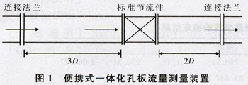
The flow measuring device adopts a standard orifice plate, and the aperture ratio β of the orifice plate is 0.640439. The lengths of the straight pipe segments between the front and rear of the standard orifice plate throttling device and the connecting flange are 3D and 2D, respectively. The actual installation method is the connection method. Blue's upper and lower straight pipe lengths are 15D and 6D, respectively. Because the flange connection is added in the upper and downstream straight pipe sections, the integrated orifice flow measurement device is a non-standard throttling device and it needs to be real-time calibrated.
Second, the standard calibration system calibration using Changchun First Automobile Group's flow standard device (Figure 2). The standard volume tube is S-25, the turndown ratio is 1200:1, the measurement flow rate is 0.48-567m3/h, the repeatability is 0.01%, and the measurement accuracy is ±0.05%. The standard flowmeter uses three sets of turbine flowmeters K-2D with a measurement range of 80 to 1500m3/h, a repeatability of 0.02%, and a measurement accuracy of ±0.1% as the flow standard. In the case of an overlapping flow area of ​​80 to 567m3/h, both the volumetric tube and the standard flowmeter can be used as flow standards. 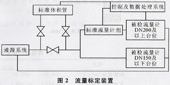
In the calibration test, the connection between the integrated orifice flow measuring device and the standard flow device is a standard flat welded flange, and the lengths of the upper and downstream straight pipe sections of the connecting flange are 15D and 6D, respectively, which are basically the same as the actual conditions of the 300MW unit. The calibration flow range is from 500 to 1000 m3/h. The calibration results are shown in Table 1. 
As can be seen from Table 1, the maximum measurement error of the integrated orifice flow measuring device is 4.09%, which cannot meet the requirements of the conventional thermal performance test of the power plant. According to the analysis, the main reason for the larger measurement error is that the flange connection at the 3D and 2D lengths of the straight pipe before and after the throttle piece generates a vortex, which changes the flow field in the pipe, and thus affects the differential pressure measurement before and after the throttle piece. For the problem that the length of the straight pipe before and after the standard throttling piece is not enough, the literature uses a series of standard nozzle flowmeters to carry out real flow calibration of the orifice flowmeter. The literature adopts an overall calibration method to obtain the flow coefficient of the flowmeter, but in practice, it is often because Straight pipe restrictions cannot be implemented. In the literature, the use of an inner cone flow meter solves the problem of insufficient length of the straight pipe section. However, if the size of the inner cone angle is improperly selected, such a flow meter has a great influence on the measurement result.
Third, the structure of the connecting flange The inner diameter of the condensate water pipe of the 300MW unit in this article is 309mm, and the outer diameter is 325mm. The connection method is DN (nominal diameter) 300mm, PN (nominal pressure) 1.6MPa, internal diameter 328mm, thickness 32mm plate type flat welding flange, at the flange joint will form a concave width 24mm, depth 9.5mm (Figure 3) . 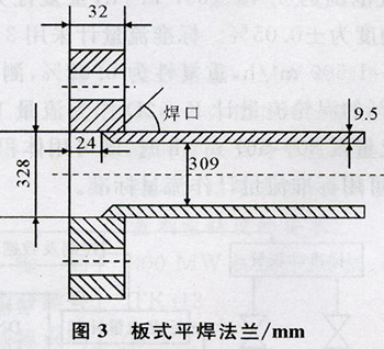
As can be seen from Fig. 3, the concave table at the flange connection changes the flow field distribution of the fluid in the pipe, thereby affecting the measurement of the differential pressure before and after the throttle piece. In this regard, the flat welded flanges are cut and ground so that all the welding grooves are on a single plane, forming a new type of flange with neck butt welding. The centerline of the flange and the pipe can be made during welding. Consistent (Figure 4). 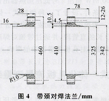
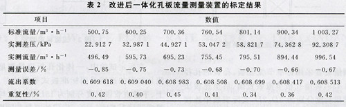
It can be seen from Table 2 that the maximum error of the integrated orifice plate flow measurement device with connecting flange is 0.85%, which satisfies the requirement of the condensate flow measurement error of the steam turbine thermal performance test (<1%). This is due to the use of a neck butt welded flange to improve the flow field distribution in the downstream pipe on the orifice plate, so that the pressure difference between the front and rear of the orifice plate is closer to that of the standard straight pipe section.
IV. Conclusion As the new portable integrated orifice plate flow measurement device has a vortex at the flange connection between the 3D and 2D lengths on the standard orifice plate and the lower straight pipe section, the distribution of the flow field in the pipe is changed and the maximum flow measurement error is achieved. 4.09%. In this regard, after changing the conventional flat welded joint flange to neck welded flange, the maximum error of the integrated orifice flow measurement device is reduced to about 0.85%, which meets the measurement error of the condensate flow in the thermal performance test of the steam turbine. The request.
Research on a New Type of Suspected Water Flow Measurement Device
According to the ASME standard, high-precision differential pressure components should be used for high-precision measurement of flow. Because the standard orifice plate has the characteristics of high measurement accuracy, wide application range, and low price, most of the existing steam turbine condensate flow measurement uses the standard orifice flowmeter. However, the traditional differential pressure flowmeter has a decentralized structure and requires high installation requirements on the site. In addition, the eccentricity of the throttle (different axiality) and the eccentricity of its accessories or annulus, as well as the measurement error of the differential pressure transmitter Affects the measurement accuracy. Fig. 1 is a portable integrated orifice flow measurement device designed according to the parameters of the No.5 low-pressure heater outlet condensate of a 300 MW unit and the size of the pipeline. The re-calibration of the integrated orifice plate flow measuring device with the modified connecting flange was performed. The results are shown in Table 2.